Showing posts with label Pi Pico. Show all posts

Thursday, 28 July 2022

Milestone for MIDISID


MIDISID has two SID chips (modern SID replacements, SwinSID Nanos) driven by a Pi Pico. It has MIDI in and audio out.

I'd hoped that this version of the boards (above) would be the final 'release' version. There are some very minor tweaks to make but I'll be building 5 of these - one for myself and four for people interested in an 'earlybird' deal. I'll try a black version too.

The firmware has taken many many hours, and it's clear that there will always be new features on the horizon. If it sells then I look forward to the ongoing development.

It's working very well, see the video below, in which it is in 'General MIDI' mode, I'm playing in the MIDI files for the DOOM levels. 


Saturday, 9 July 2022

Picoterm v1.1 released, choice of colours and Turbo Pascal 3

A user reported that when using Turbo Pascal 3 on his RC2014, scrolling within the source code editor wasn't working.

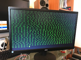
My way of investigating issues with escape codes is to load up a modified version of PicoTerm which prints every character as a number. I also had the RC2014 connected to a terminal on my Mac, so I could still use TP3.

Investigating these numbers showed that the scroll up / scroll down (and also the scrolls that happen when you cursor to the top or bottom of the window) all rely on two escape codes that PicoTerm didn't support:

<esc>[1L

and

<esc>[1M

These are not listed on the Wikipedia ANSI escape code page, which has been my main reference. PicoTerm didn't support them before today. (And neither did PiGFX as far as I can see.) But they do work within minicom and Teraterm, so it seems that they're reasonably 'standard'.

It appears that these codes mean 'insert a line at the cursor position, scrolling everything down'  and 'delete a line at the cursor position, scrolling everything up'.  I have assumed that the number is the number of lines to scroll, although I can't be sure about this until I find some documentation.

Picoterm is built with scrolling in mind - each line of text is a structure, and the display buffer is an array of pointers to these structures, so scrolling is no more than switching 30 pointers around, and clearing a line.

So adding support for these escape codes was straightforward. Each is a variation on the scroll that is already used when the cursor reaches the bottom of the screen.

Here is a quick demo, first showing another new feature of the textmode (mono) version of PicoTerm - the ability to switch colour on startup, according to button A, B or C being held on power-up. White, Green or Amber. 

Then a quick demo of the scrolling up and down within Turbo Pascal 3's editor.

More information about PicoTerm generally, and downloads, are here.


Tuesday, 21 June 2022

Clock, temperature and humidity display using Badger2040

 The Badger2040 is a RP2040 with e-ink display. Or possibly an e-ink display with a RP2040 on the back:

It has other goodies like 2Mb of flash ram, some buttons and lots of connectors such as a battery connector, stemma/qwiic socket and breakout pads for various serial connections. And USB-C for programming and serial in/out.


I've added an Adafruit temperature / humitity sensor using the stemma connector. This particular sensor is AHT20. The only negative thing about that for this project is that it has a fixed i2c address, and I would have liked to hook up two, one for indoor and one for outdoor temperature. I'll have to buy another which is a different type and has a different address.

For now my program is reading the data from the one sensor and displaying the temp and humidity. This took me some time because the libraries for this sensor (that I could find) were either circuit python or arduino.  If you want to use either of those things, you only need to write a couple of lines of code. For C (or in this case C++)  I had to write my own code starting with i2c_write_blocking() and i2c_read_blocking() and referring to the AHT20 data sheet and the Arduino library. An annoying bug (on my part) meant that I spent more hours than I should have on that.

With that done it was a breeze to print the stuff to the screen (using the Badger C++ example code). I wrote the clock from scratch using the time.h functions within the Pi Pico C SDK to access and process the hardware timer - get_absolute_time(), to_ms_since_boot() etc.  I've got the up and down buttons adjusting the hours or minutes up or down, with buttons A and B switching between adjusting hours and minutes. 

It looks great. The e-ink display is very easy to read in any light and uses no power, except when updating.  I've got the screen updating every 30s or if you push a button to adjust the time.  Another curious thing about this type of display is that it keeps displaying its contents even with power disconnected. Meaning if you wear it as an actual badge, you don't need to power it once it's displaying what you want!

The battery pack that comes with the Badger is a bit chunky (two AAAs inside). I don't know how long that lasts, but I might use a small lithium battery instead, that can be stowed more easily on the back.

UPDATE

I've now got it running off my first found-free-in-the-street  battery. This is a relatively small one compared to the 500+ mAh ones Big Clive has been finding but it is nice and flat and it has been powering another pico project of mine and showed no signs of flagging. I'll be fascinated to see how long it runs the Badger!

Another improvement I've made today is to make the clock periodically write some details to the flash memory, so that if power is removed, it'll start up displaying the same time as it did when disconnected. That saves a lot of button-pressing after a battery change.

I've been struggling with writing to the flash memory on the Pico and on this device, but today I solved my issue. Basically don't have USB stdio enabled while trying to write to the flash.


Thursday, 21 April 2022

Having got so far with the MIDI SID project, I had this real mess of wires and boards. Then I started to add to the carnage with knobs and a display.  

The problem was that if something stopped working I couldn't be sure whether it was because I'd got something wrong, or had just jogged a connection.

Happily, prototype boards are so cheap that you can order something without worrying about the cost. This isn't even really a prototype yet, not all of the components are on the board. I just wanted the Pico, two SIDs (in this case swinsids) and the MIDI in circuit soldered firmly in place so that I could experiment with knobs, buttons and displays, and develop the software without fear of breaking it by jogging the desk!


To get you up-to-date if you haven't seen my ramblings about this, I'd love a box with MIDI input, SID chips inside, audio out, and simple controls. I'd like to be able to play a .mid file into it, or plug in a keyboard, with options for polyphonic or monophonic output. (I've done some of this using a C64 and MIDI cartridge, but it'll be good to have a standalone box.)  I'd like to try a larger version with enough SIDs to be able to map each midi channel to a voice. Maybe in time I could add the components needed to support real SIDs, but being able to use ARMSIDs would be good as they're a great replacement. (I'm not sure that it's ethical to encourage anyone to use precious real SIDs in something like this.

Quick demo of the thing working (just one channel in, one voice playing). I've got Logic Pro playing a simple tune, with a USB-MIDI converter allowing me to plug that into this board. 

If you're interested in the project, I'm going to use the hashtag #MIDISID on Twitter. 

Sunday, 6 March 2022

Minstrel the 4th is a modern recreation of the Jupiter Ace, a lesser-known home computer from 1982. It's notable for its use of Forth rather than BASIC which was common at the time.

The Ace had a ZX Spectrum-like rubber keyboard. The Minstrel's is an improvement but its small tactile switches don't really allow for fast typing.

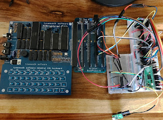
The Minstrel and similar computer scan the keyboard by reading a group of hardware ports which correspond with half-rows of the keyboard. They expose the bus as an expansion port, so it's possible to intercept those port reads. Here's my working prototype, it uses quite a bit of logic. The Pico's main job is to act as a USB host and allow a modern keyboard to be plugged into its own micro-USB port. and maps the keypresses it receives to the appropriate rows and columns of the Minstrel's keyboard matrix.

It's not only the size and arrangement of the keys that limit typing speed, but the fact that the keyboard matrix is scanned every 1/50th second and then not buffered. So even with modern key switches, this makes typing on computers like the Ace, ZX81 and Spectrum is a bit of a plod. It's easy for the Pico to buffer the keyboard input, and present it to the Minstrel one key at a time, at a speed that it can handle.

This also opens up the possibility of connecting a serial terminal to the device to allow listings to be pasted to the Minstrel. It also means that anything you type using a USB keyboard can be echoed to the terminal giving you a paper tape of  In the top picture you can see that the finished product has a USB-FTDI adaptor attached for this purpose.

My interface is now in production in small batches, please contact me for details.

Saturday, 18 December 2021

Dimming an RGB lightstrip using a Tiny2040 (Pi Pico)

 This is just a simple experimental project to try out Pimoroni's Tiny2040 for the first time.


In order to dim LEDs we have to use PWM; change the duty cycle of a square wave. The 2040 chip handles this and so this program is really simple, it just sets up PWM on one pin and handles two inputs, one for brighter, one for dimmer. 

The harder part was controlling 12v LED strip using a 3.3v output. I've used a small transistor to amplify to 5V and then a mosfet to step that up to 12v. A 7805 gives us a 5v supply to power the microcontroller and to use in the amplification circuit.

It would be possible to generate three square waves with independent duty cycles, and thus have smooth colour changing with the RGB LEDs.

Friday, 17 December 2021

PicoTerm, terminal application for Raspberry Pi Pico, supported escape codes and user-definable characters

PicoTerm is an application for the Pi Pico which provides a serial terminal with VGA output and USB keyboard input.


It was developed for the RC2014 and therefore is configured for that computer; eg 115,200 baud and the RC2014 logo at startup. However, if you'd like a custom version, please get in touch.

The Pico has resources that allow for a 640*480 output with a character mode, or 320x240 with full  32,000 colour.

I've recently added support for uploading user-defined character data. I've made this page in order to document the escape codes currently supported, along with information about the new UD character functionality.

Here is the list of supported escape codes, followed by the information about defining characters.

  • \ESC[?25l | Cursor invisible
  • \ESC[?25h | Cursor visible
  • \ESC[H | Move to 0-0
  • \ESC[s | Save the cursor position
  • \ESC[u | Move cursor to previously saved position
  • \ESC[-Row-;-Col-H | Move to -Row-,-Col-
  • \ESC[0K | Clear from cursor to the end of the line
  • \ESC[1K | Clear from the beginning of the current line to the cursor
  • \ESC[2K | Clear the whole line
  • \ESC[2J | Clear the screen and move the cursor to 0-0
  • \ESC[-n-A | Move the cursor up -n- lines
  • \ESC[-n-B | Move the cursor down -n- lines
  • \ESC[-n-C | Move the cursor forward -n- characters
  • \ESC[-n-D | Move the cursor backward -n- characters
  • \ESC[0m | normal text (should also set foreground & background colours to normal)
  • \ESC[7m | reverse text
  • \ESC[0J | clear screen from cursor
  • \ESC[1J | clear screen to cursor
  • \ESC[3J | same as \ESC[2J
  • \ESC[nS | scroll whole page up by n rows (default 1 if n missing)

40 col colour only: (sequence is ignored, no effect in 80 col b/w)

  • \ESC[38;5-n-m | Set foreground colour to -n- (0-255)
  • \ESC[48;5;-n-m | Set background colour to -n- (0-255)
  • \ESC[38;2;r;g;bm | Set foreground colour to r/g/b (values 0-255, scaled by picoterm to 0-31 to give 32,000 colours)
  • \ESC[48;2;r;g;bm | Set background colour to r/g/b (values 0-255, scaled by picoterm to 0-31 to give 32,000 colours)
80-col textmode version only: (from version 1.1)
  • \ESC[1L | Insert line at cursor position, scrolling down from the cursor's row
  • \ESC[1M | Delete line at cursor position, scrolling up to the cursor's row

User-definable characters

C/PM (which is widely used on the RC2014) uses 7-bit ascii characters, which means that there are 128 characters (128-255 inclusive) unused and available for defining by the user. In the case of the colourmode  version of Picoterm, the character data is simply stored as pixel data (foreground colour/background colour, 8 bytes per character) and drawn to the screen when needed, which means that the 'reverse graphics' doesn't rely on those reverse characters being defined, and therefore works on the default fixed characters and any that you define.

Note that this functionality is present in picoterm colour v0.2.0 onwards, which is available here.

  • \ESC[?-n-U | followed by 8 bytes, which will be inserted into the user-defined character space for character n (n can be 128-255 inclusive)

When displaying custom characters, the current foreground and background colours apply, these being reversed if reversed graphics is on.


Here is the simple basic program used in the screenshot above to display pacman: (yes, it's possible to use a loop to define the four characters, but beware of MS Basic's tendency to add a space when using STR$. It's expanded here for readability.)

10 PRINT CHR$(27);"[?128U";

20 FOR C=1TO8

30 READ A

40 PRINT CHR$(A);

50 NEXT C


60 PRINT CHR$(27);"[?129U";

70 FOR C=1TO8

80 READ A

90 PRINT CHR$(A);

100 NEXT C


110 PRINT CHR$(27);"[?130U";

120 FOR C=1TO8

130 READ A

140 PRINT CHR$(A);

150 NEXT C


160 PRINT CHR$(27);"[?131U";

170 FOR C=1TO8

180 READ A

190 PRINT CHR$(A);

200 NEXT C


205 PRINT CHR$(27);"[38;5;11m";

210 PRINT CHR$(128);CHR$(129)

220 PRINT CHR$(130);CHR$(131)


230 END


1000 DATA 15,63,127,127,255,252,224,252

1010 DATA 0,192, 224,224,128,0,0,0

1020 DATA 255,127,127,63,15,0,0,0 

1030 DATA 128,224,224,192,0,0,0,0


Thursday, 9 December 2021

Electronic Dice with the Pi Pico

This was my first project with the Pi Pico. It's a 'Hello World' for hardware/software.


The real reason for two buttons is that I already had the box drilled and fitted with the two buttons for a different project. It made sense to switch the power using an arcade button, because it's automatically switched off when you let go of it. The second button grounds the 'run' of the Pico, which means that it performs the shuffle and display once more. In reality, just the one power button would do, because letting go of that and pressing it again does the same thing as the 'run again' button.

I wrote the software in Micropython because this was my introduction to the Pico. More recent projects use C which suits me much better.


* That should probably be electronic die, because one die is shuffled and displayed. The pico has enough pins to shuffle and display 3 dice, and probably many more with a bit of logic to decode the binary numbers 0-6 (3 GPIO pins) to 7 LEDs.

Sunday, 7 November 2021

Terminal software for the Raspberry Pi Pico

 I am very proud to have been involved in this hardware / software project with Spencer, creator of the RC2014.

The Pi Pico is a powerful microcontroller, it runs at 133 Mhz by default but can be overclocked to 400Mhz. It has two cores and eight state machines. The state machines have their own assembly language and can independently manage i/o or dma tasks.

It is capable of buffering and generating a video signal, VGA or DVI. Using the TinyUSB library it's capable of receiving USB input.

With these features, it's the perfect candidate for this task. With a few supporting components and the software/firmware installed, it's acting as a serial terminal with USB keyboard input and VGA output. 

The RC2014 is a retro-style computer running a Z80 at up to 7.372Mhz. It does require you to use some kind of terminal for input and output. Usually this is a terminal program running on a modern computer and that's where this new module comes in. It allows the computer to be used standalone, as seen here with CP/M running on the RC2014. It communicates with the computer using UART serial via two of the Pico's GPIO pins and the Rx and Tx lines on the RC2014 bus. It receives keyboard input via the micro USB socket on the Pico (with an OTG adaptor. NB TinyUSB on the pico seems to work with some keyboards and not others.)
The project required custom software to be written for the Pico in C. 

The video output is taken care of by libraries, although the example code certainly did take a while to understand. That part of Textmode PicoTerm largely draws on the text mode example code. 

The USB handling uses TinyUSB. The Pico must act as a host (with the keyboard connected via an OTG adaptor). 

That leaves the terminal functionality. You need to maintain a buffer to store the characters (because the video functionality makes callbacks, requesting the data for each scanline as it's generated). Scrolling is an important  feature of a terminal, so I created a structure to store the character codes for each row of characters, and an array of pointers to those rows. So scrolling is a matter of shuffling 30 pointers rather than 2400 characters. 

One of the Pico's cores can handle the scanline generation for the video while the other listens for characters sent from the computer and from the keyboard, buffers and handles those. [update - with the textmode Picoterm, polling was fine and works without dropped characters. With the newer colourmode PicoTerm, because of the increased load of putting characters on the screen, it was necessary to implement interrupts on Rx to receive and buffer each incoming character].

As well as just feeding characters to the screen and scrolling when necessary, it's also important to parse and handle certain escape sequences.  These codes can position the cursor on the screen or change the attributes (eg reverse characters). The full list of sequences that we've implemented so far are here on the module's documentation page.